Introduction
You are perhaps familiar with the terms baffle step and box diffraction. But what is this exactly? The short story is that a driver mounted on a box will radiate sound uniformly in all directions at low frequencies where the wavelength is much longer than the dimensions of the box. This is called 4 pi radiation. At high frequencies, the surface of the box prevents the sound from propagating behind the speaker and this concentrates the energy in a half sphere, also called 2pi radiation. The concentration implies an average increase of the forward sound pressure of 6dB. The baffle step is essentially how and where in frequency this transition happens.
Many have seen Harry Olson's now legendary 1951 paper with graphs of the baffle step for various cabinet shapes. Here, a cylinder is the worst and an sphere is the best. In this blog post, we dig deeper into this phenomenon and study these two extreme cases along with a real loudspeaker.
Case 1 - Cylindrical cabinet - worst case
We can simulate the sound field around a cylinder using a 2D axisymmetric model in COMSOL. The cylinder has a diameter of 0.8 m and a height of 0.4 m. At the top center, a tiny disk-shaped membrane produces a short acceleration pulse, approximating a point source emitting a delta-like pressure wave.
According to Huygens' Principle, the pressure pulse propagates initially as an expanding spherical wavefront, visualized as the initial positive (red) circular pulse (see the animation below).
When this wavefront reaches the sharp edge of the cylinder, a diffraction phenomenon occurs. The corner acts as a secondary point source, again following Huygens' Principle. As the primary wavefront 'bends' around the edge, its pressure is reduced. This happens because the wavefront loses the support of the baffle (boundary); the sudden expansion into the surrounding medium behind the baffle creates a local negative pressure (a.k.a. rarefaction wave). This negative wave subtracts from the primary pulse and propagates as a new secondary, negative wavefront from the corner. This subtraction of pressure is essentially the baffle step loss in a nutshell. At the corner, the pressure is halved—which is exactly a -6 dB drop. This happens because the sound, which was previously radiating into 'half-space' (blocked by the baffle), suddenly 'sees' the full space around the cabinet and has to spread its energy much thinner.
(Comsol file download)
If you ever wondered why we can hear a person talk behind a corner then you just got the explanation and now know that it is closely linked to the baffle step.
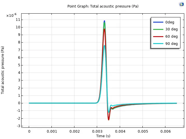
Lets review the the pressure impulse responses picked up by microphones in the 0, 30, 60 and 90 deg positions (relative to straight up which is our on axis):
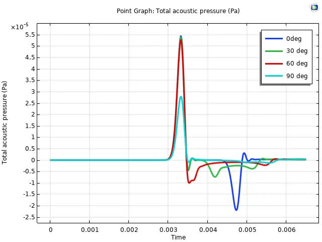
We see that all mics record a positive pulse at the same time since they are at the same radial distance from the source. The on-axis mic then receives a second, negative pressure pulse from the corner with a delay corresponding to the 'time-of-flight' for half the baffle width (approx. 1.2 ms for a 0.4 m travel). Note that this secondary negative pulse is about half the amplitude of the initial positive pulse—exactly as expected from the theory.
We can perform a simplified Matlab calculation to see how this looks in the frequency domain. We have the primary positive pulse at time zero (constant spectrum, magnitude 2). The delayed negative pulse is represented as a subtracted exponential function (magnitude 1). This model ignores the secondary diffraction from the edge at the back of the cylinder. Plotting the result in dB gives us the classic baffle step curve "
fv=linspace(0,2e3,1000);
bw=0.8; % baffle width
c = 343; % speed of sound m/s
H = 2 - exp(-2i*pi*fv*bw/2/c);
plot(fv,db(H),LineWidth=3);
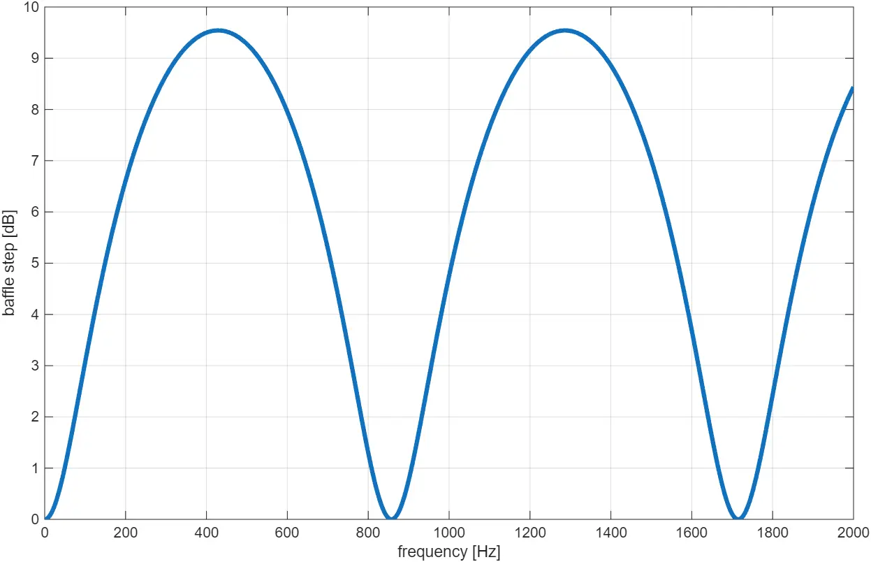
The graph is essentially the theoretical on axis baffle step and matches Harry Olson's graph although we use a linear frequency scale to highlight the periodic nature: It is periodic with 857 Hz which is the frequency with a wavelength equal to half of the baffle width (or actually diameter in our cylindrical case). At zero frequency (DC) we have no gain and at 429 Hz we have constructive interference between the direct primary pulse (red) and the negative pulse (blue) from the corner. At this point, there is about 9.5 dB baffle step gain. The next destructive interference is at 857 Hz where we a back to 0 dB gain and it continues periodically.
Why not just equalise the response?
I am glad you asked. Such response being periodic in the Frequency Domain with repeating dips and peaks is actually theoretically impossible to EQ using passive or active analog filters. Such filters use roughly two components for each peak and dip that has to be EQ'ed and here we have an infinity. Of course, the cylinder with a tiny sound source is the pathological worst case and in real applications, the response rippling does not go on forever. Anyway, even if equalise it perfectly then we have another problem as we shall see next.
The Polar Response
The time domain plot green curve shows the response from the 30 deg mic. Here, we get the same primary pulse but the negative comes sooner and is dispersed more. For the 60 deg, it comes even sooner. This change of the delay of the negative pulse obvious changes the frequency response relative to the on axis response. This shows why the on axis baffle step response is directly linked to the polar response of the loudspeaker.
At 90 degrees we see something surprising: the listener only gets hit by the primary (red) positive pressure wave, although cut in half amplitude due to the diffraction of the corner. This means that we have no baffle step and a theoretical flat response with not dips and peaks. The 90 deg response is not 100% flat in our case, since we also have the secondary diffraction from the edge on the back of the cylinder, i.e. the diffraction of the diffraction. However, such nice flat response in 90 deg does not help so much since we typically want to equalise the loudspeaker response flat on axis and that will mirror the baffle step to the polar response.
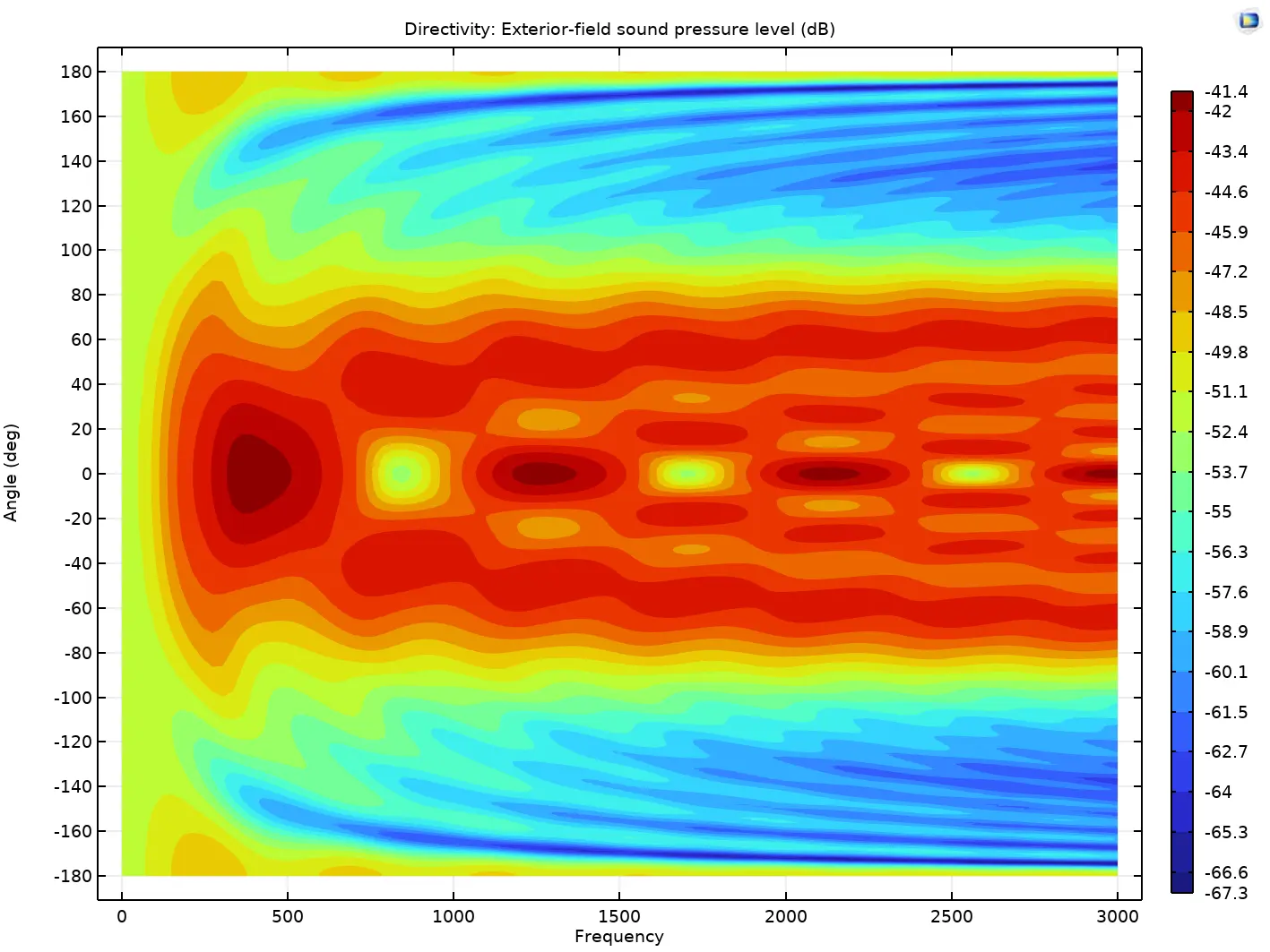
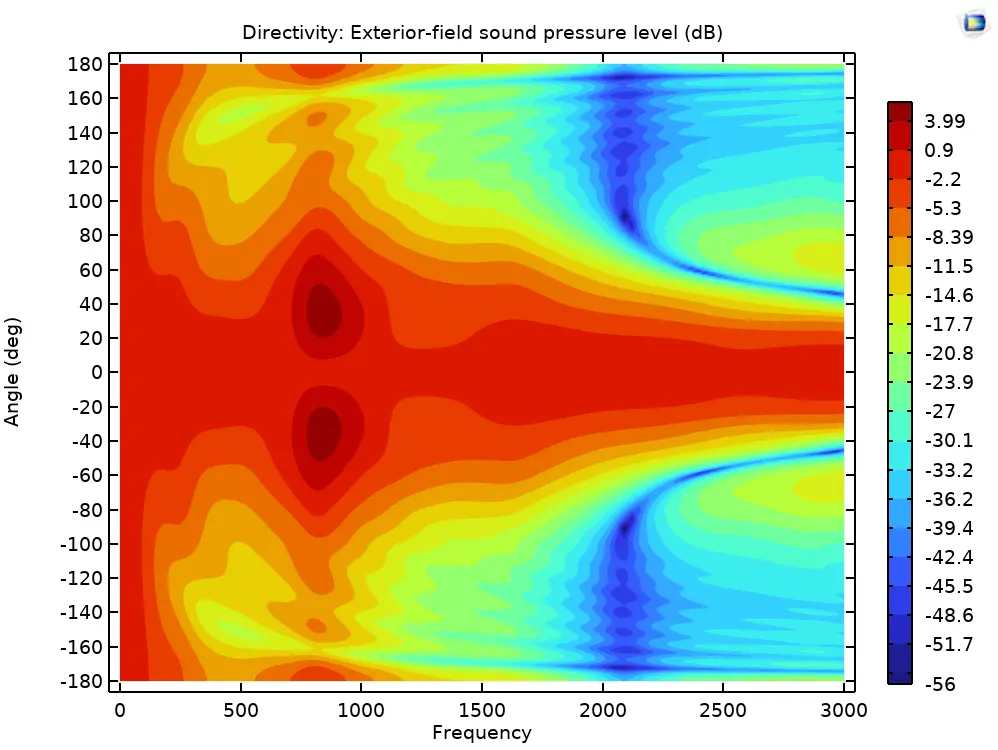
We now let Comsol simulate our example in the frequency domain (which is a lot faster and more precise than the transient time domain). This time we do a directivity plot with frequency on the x axis and polar angle on the y axis. The color represents the sound pressure (un normalised). By looking at the 0 deg horisontal line across frequencies, we recognize the on axis baffle step with periodic peaks and dips, eg. first peak at 429Hz (dark red) and next dip at 857 Hz. The dip to peak ratio is about the 9.5 dB we found earlier.
The 90 deg cross section has nearly the same sound pressure as expected. Similarly, the 180 deg direction has a nearly flat response.
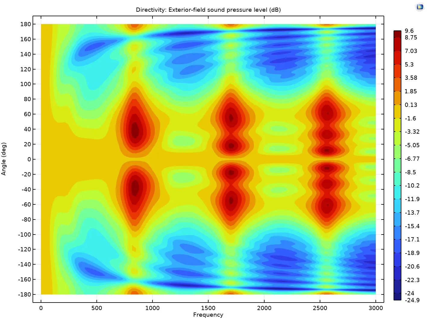
If we plot the same directivity but now normalised to the on axis response (which is normal practice and represents that we have EQ'ed flat on axis), we get more drama and the baffle step is reflected in up to 9.5dB peaks off angle where the on axis has dips. Now this looks really ugly:
What did we say about tweeter mounting in the data sheet?
Fun fact: the cylinder with a small sound source example here is actually applicable to the questions of how to mount a round face plated tweeter in a baffle. If the faceplate is not 100% flush with the baffle then we get diffraction ripple similar to what we analysed here ( a cylinder sticking out of a plane and with a small sound source in the center).
What happens when we measure in the near field?
It is tempting to measure the ludspeaker with a mic very close since we suppress the influence from the room around the speaker. However, does this reflect the sound field picked up from further way in anechoic surroundings? As you may have guess, no it does not. The close near field mic position gets a very strong direct sound from the speaker driver due to the close proximity (very short path) but the secondary negative wave from the box edge is much weaker as it is generated further away, or rather represents a much longer path of one baffle width. Hence the near field mic in our example will show a trivial flat response. The baffle step disappears in the near field because the microphone only sees the driver as a source and not the secondary diffraction sources. This may come as a surprise to many.
Consequently, we have to measure a loudspeaker in the far field to capture the box diffraction effects. A good rule of thumb is a distance equal to 3 times the largest dimension of the box.
Case 2: an Sphere - Best Case
The old Olson paper showed that an sphere is about the optimal shape. Lets explore that.
We have no visible diffraction from the box and the red waveform nicely just bends around the sphere. This also gives the speaker a wider dispersion as we can see from the normalised polar:
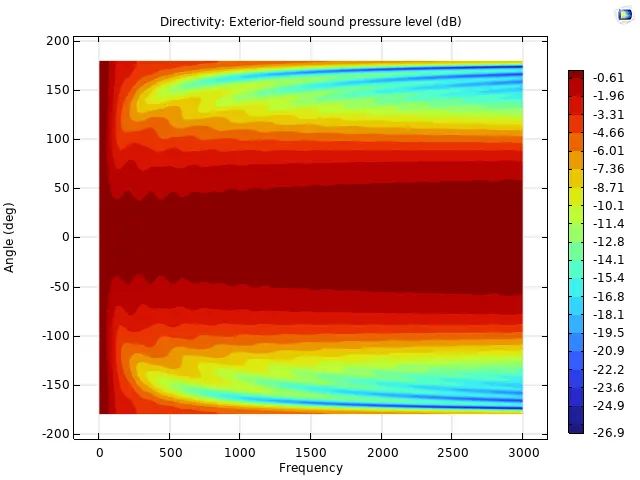
We see a very smooth baffle step going smoothly to + 6dB with minimal ripple. What is not to like :-). Such response is easy to equalise using a passive filter.
The clean response is also obvious from the time domain, again the 0, 30, 60 and 90 deg mic positions:
This shows why rounding of corners is so effective, although this sphere is an extreme case.
Should I then round the front or the back of the cabinet?
The edges closest to the sound source are causing the most diffraction. the edges at the back of the box are only causing secondary or tertiary diffraction and the contribution is limited.
With this knowledge at hand, it is funny to see so many beautiful and expensive high-end speakers with nearly flat front baffles and nicely rounded backs...
A more realistic example: a larger driver membrane
The previous cylinder case used a very small sound source, ie a point source. This is indicative for when using a smalle tweeter. If we now use a disc of 20 cm diameter like an 8" woofer, the diffraction response from the sharp edge becomes smoothed out in time which tends to reduce the rippling of the baffle step towards higher frequencies. However, the larger membrane also makes the radiation pattern more narrow (an 8" woofer does get a narrowing directivity). Here is the FEA simulated baffle step on axis for this case:
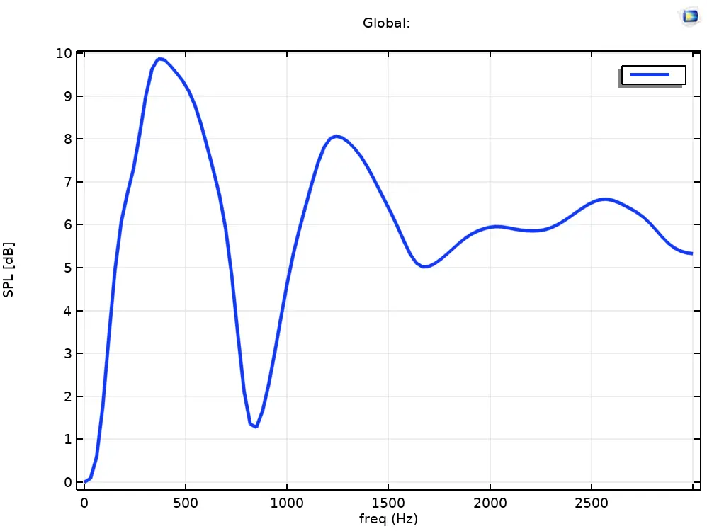
We see that the first pak still is around 9.5dB whereas the following peaks and dips narrow in and approach a +6 dB plateau.
The normalised directivity pattern:
we still see a very uneven dispersion at the first baffle step peak at 857 Hz with off axis at 40 deg peaking about 4 dB but above in frequency we get a more smooth narrowing without off axis peaking above on axis. We can say that the narrowing directivity of this larger woofer does not illuminate the corners at high frequencies and hence reduces the impact of the edge diffraction.
The typical monkey coffin box with rectangular panels and baffle has even less ripples because the baffle edges have varying distance to the driver (as opposed to the cylinder where the edge diffraction from all round comes at the exact same time and gets reinforced). See Olson's case I (cube and points source) and compare to our worst case cylinder case. Moreover, most cone drivers have a cone shaped membrane (hence called cones) and this acts a bit like a horn or waveguide which narrows the directivity further and thus sends more sound forward on axis at certain mid frequencies.
A real Loudspeaker: SPK16
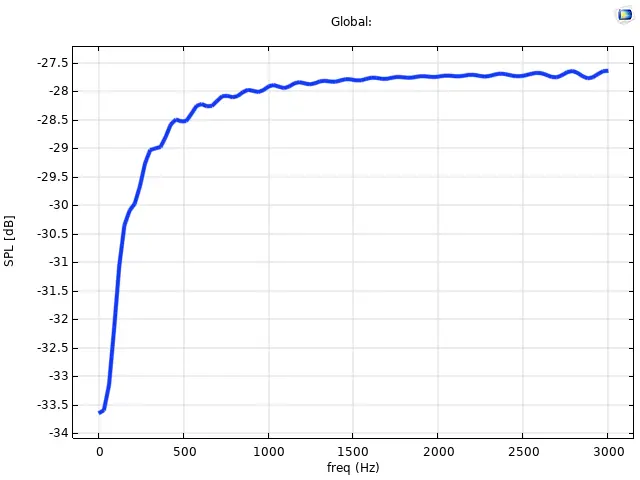
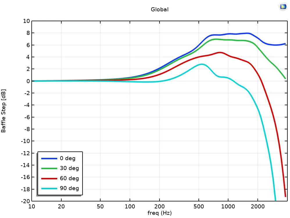
A complete 3D FEA model was used to develop our SPK16 reference design (now available as a kit) . The baffle step was used as part of optimising the bass tuning together with the woofer crossover filter even before any prototype was built. SPK16 has a 250mm wide baffle but with a generous edge roundover (fillet) with 50 mm radius. We see that with a well rounded box and a real conical membrane we have a quite smooth baffle step that only peaks at 8 dB- The dip at 2 kHz naturally indicates the crossover point. The woofer has wide and smooth dispersion up to this frequency.
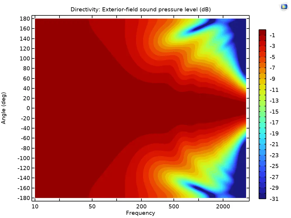
The 3D horisontal directivity plot also confirms that we have wide dispersion to 2 kHz and that first major narrowing is at 600 Hz where the on axis baffle step flattens out:
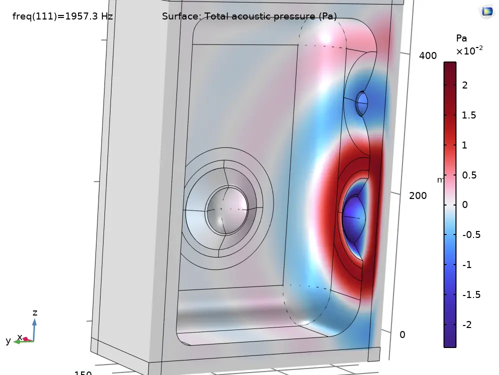
The 3d sound field is revealed by the 3D FEA model:
Conclusion
The baffle edges act as a secondary sound source that echoes the sound emitted by the driver. This produces both a frequency response and directivity aberations. We showed that the diffraction is a delayed and echoed phantom source and this could easily be imagined to interfere with the perception of the sound stage. It is best to either have a very narrow or even no baffle (yes some do that with succes), or an extremely wide one ( preferably mount your drivers flush in your wall) or apply generous rounding of your box edges. But for normal free standing boxy speaker we have to deal with the baffle step in the design process. It affects the directivity pattern, choice of the woofer filter and choice of crossover frequency.