Introduction
There is widespread confusion regarding the terms phase and time-alignment of loudspeakers. Moreover, the fundamental concepts of latency, delay, phase-delay and group delay are often conflated. Another poorly understood concept is the acoustic center. In this little blog we will set things straight for what matters for designing a multi-way speaker with non-coincident drivers.
Lobing
In the crossover frequency region, there will be two drivers radiating the same signal from different locations separated by some center-to-center distance on a speaker baffle. The sound sums up in the far field in a pattern with peaks and cancellations depending on the direction. The direction determines the difference in the travel path of the sound to the listener. This changes phase shift between the drivers, and we get constructive or destructive interference depending on the direction of the listener and the frequency. Such radiation pattern is often referred to as lobing: certain directions have maximum radiation (lobes) and in between we have complete cancellation. Since the pioneering work of Linkwitz and Riley most prefer crossover filters that has a main lobe pointing straight forward [1]:
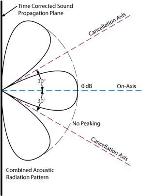
The legendary Linkwitz-Riley filters ensure that the high-pass and low-pass outputs are in phase at all frequencies and are exactly 6dB down when they meet at the crossover frequency.
The influence of the driver response and its physical offset
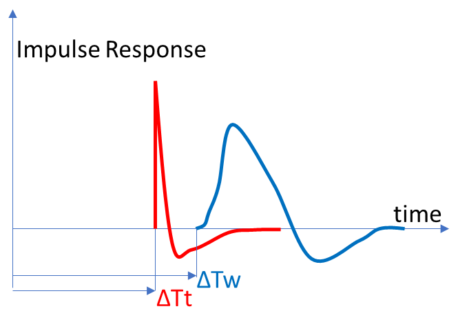
The response of a driver is minimum phase. A minimum phase filter has the least phase shift for a given magnitude response, hence the name. Any response can mathematically be decomposed into the product of a minimum phase part and a so-called excess phase part having unity magnitude response (aka all-pass response). For a driver response, the excess phase part of the response simply is a delay corresponding to the time of flight for the sound to the listener. In other words, the excess phase part is simply the latency time ΔT until we first observe a change in the response. For woofer mounted in the same baffle as a tweeter we will typically observe a larger latency time compared to for the tweeter. This is because the tweeter dome may protrude beyond the baffle whilst the woofer cone is radiating from below the baffle front plane. For example, the impulse responses of a tweeter and woofer may look like:
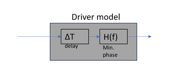
Note also that the driver response is heavily influenced by the diffraction from the box it sits in (the baffle step) as well as the box alignment chosen. However, both these effects preserve the minimum phase property. In any case, we can model our driver response as a pure time delay (time of flight) and a minimum phase filter:
Crossover Design
A common mistake is to design a textbook perfect crossover filter and apply it to the drivers without considering their individual responses. We need of course to control the total electrical to acoustical transfer function to ensure that the responses sum up correctly and that the summed response is flat on axis. Consequently, the crossover filter needs to comprise some equalization of the drivers used. Conceptually, we equalize the response of the drivers flat to a nominal gain in a wide frequency band covering their pass band and well into their stopband. This EQ response is then multiplied with the mathematical text-book crossover target responses that sums to a perfect flat magnitude response. In practice, the mathematical and EQ responses are merged into a single electrical network or filter structure.
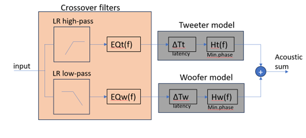
The inverse of the driver minimum phase response is also minimum phase. This means that there is aways a stable and realizable EQ filter. However, using such minimum phase EQ filter we preserve the latency time. This is irrespective of the driver’s actual magnitude response including whatever baffle step from the box – that is a very important point to note. In the case of a perfect minimum phase EQ, the combined EQ and driver impulse response will look like:
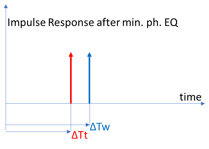
As we see, the latency time of each driver is preserved, and the driver responses are now both pure delta impulses of the same magnitude but delayed by the respective latencies.
In the case that the EQ filter also compensate for differences in the latency time between the drivers by having an excess phase part in the form of a pure delay, we get a perfect radiation pattern with the main lobe pointing straight out. By reversing the polarity of one driver we can verify that we get a null on axis (the reverse null).
However, compensating for a latency delay is very complex to do when not using a DSP. The typical crossover filter used in passive speakers is minimum phase, i.e., It has no excess phase part and thus no latency. In this case, we cannot correct for the latency time and difference since the latency time between woofer and tweeter as measured on axis will cause the lobes to tilt and no longer point straight. There are in general 3 solutions to this problem when not using a DSP:
1. Make the low-pass and high-pass slopes a bit asymmetric to compensate for the latency mismatch of the drivers. This is what designers typically do when they tweak component values to get a clear reverse null, e.g., when using Vituix CAD.
2. Introduce one or more all-pass filters in the path of the driver with the shortest latency (typically the tweeter) to compensate the latency time difference around the crossover frequency. This can be done as a passive LCR network in a passive speaker. However, this is rarely seen in the wild and requires more components. An all-pass filter can approximate a pure delay in the frequency band of relevance around the crossover frequency.
3. Redesign the baffle and/or waveguide to adjust the latency discrepancy. To assess the desired latency compensation, one can insert delay compensation in the crossover design tool (e.g. VCAD) and find the value that allows the most attractive crossover and then redesign the baffle/waveguide. This is probably what some often refer to as a ‘time-aligned’ speaker.
All the above methods can result in a flat on axis response and a nice main lobe pointing straight (having a nice reverse null). However, all these methods result in that the summed on-axis response is an all-pass response which exhibits non-linear phase, i.e., the summed acoustic signal on axis is not simply a delayed version of the electrical input. Instead, we have more phase delay below the crossover frequency than above.
Knowing the exact latency time directly is not strictly needed to follow the above 3 methods. However, all methods require that the individual driver responses to at least one observation point is measured and preferably also including measurements for a basket of off axis points. It is simply hard to overstate the importance of measuring your speaker.
What is a so-called time-aligned speaker?
Even if you use method 3. Where the baffle is designed to compensate for the latency time difference of the drivers we will, contrary to our intuition, not generally get a linear phase (aka pure delay) where all frequencies arrive at the same time. The reason is that the sum of the low and high pass filters of the textbook crossovers result in an all-pass response with a generally nonlinear phase. Using analog filters, only a first order crossover sums up with linear phase. In addition, there are a few exotic analog solutions that result in linear phase: one being the filler driver by B&O from the 1970’ies which uses an extra driver driven by a band-pass filter (their top model used 5 drivers). Another exotic solution is the class of delay-derived filters by Lipshitz and Vanderkooy. However, they require a pure delay which is extraordinarily difficult to do in analog. In practice, true phase linear speakers using higher than first order crossovers can only be done using complex DSP filtering (e.g., Kii Three) .
Consequently, it is a misunderstanding that method 3 (equalization of the latency times by physical design of the baffle/waveguides) results in a so-called time-aligned loudspeaker in the sense of being linear phase.
How to measure the latency?
The latency can be found from the impulse response as the first point in time where we see a change away from zero.
However, this method is sensitive to noise and in the case of a woofer with a low bandwidth, the initial part of its impulse response is very slow (see the figure above) and thus hard to assess where it begins. A better method is to take the measured response and decompose into minimum and excess phase parts and derive the latency from the excess phase part. However, this requires a bit of complex math to do and is not a standard part of common analysers. Driver manufacturers could consider including measurement of the latency time as part of their data sheets. However, it will be difficult to compare results from one setup to the other since the used microphone, baffle and chamber influence the result. Moreover, the reflections from the room or chamber will corrupt the result. To avoid that, we typically used gated impulse responses to chop off the reflections. However, such gating will subtly introduce excess phase and thus lead to an error in the estimation of the latency time. The gating is obviously also causing errors in the estimated magnitude response but that is a well-known fact.
Alternatively, the latency time can be found by finding the shortest path of wave travel from the voice coil to the observer. One must here observe the speed of sound of the different materials used, the voice-coil former and cone material. To complicate matters more, the speed of sound depends on the geometry of the mechanical structure: a shallow cone has a low speed of sound compared to a steep and deep cone. The speed of sound is very high in the former since the wave is longitudinal. For a hard dome tweeter, a good approximation is to measure the distance from the tip of the dome to the observer since the time of flight from the voice coil can be ignored due to the very high speed of sound in the hard materials. Consequently, and contrary to common intuitive belief, vertical alignment of the voice coils does not in general result in the same latency time on axis. This often leads to an over-compensation of the latency e.g., when using a very stepped baffle.
What about the acoustic center?
Many would now be surprised that we have not yet touched upon the concept of the acoustic center. The simple reason is that our presented analysis shows that all what we need to care about is the measured response of the driver to an observation point on axis.
Another good reason is that the concept of the acoustic center is not at all as well defined as everyone thinks and to quote [2]: The idea of replacing a real, extended source by an equivalent point source from which outgoing wavefronts appear to diverge is deceptively simple, and various procedures for determining the position of such a source give in general different results.
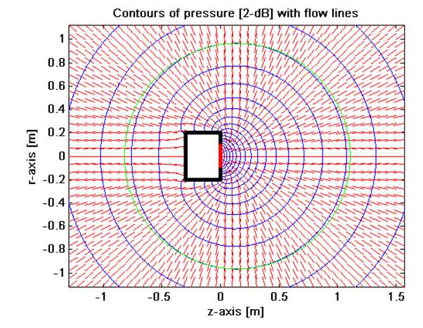
One simple definition is the point from which we get the closest match to the inverse distance law saying that the SPL falls inversely with the distance to the acoustic center. This is the same as finding the center of curvature of the equal-loudness contours. For a pulsating sphere, the acoustic center is trivially in the center of the sphere [2]. However, a vibrating piston on a box makes things more complex. This can be illustrated with Figure 13 from [3] where we have a moving piston at the end of a cylinder at 10Hz. The green curve approximates an equal-pressure contour and has its center at z=145mm, i.e., in front of the piston. This position is stable up to around 200Hz according to [3]
The low frequency acoustic center is relevant when placing e.g., a subwoofer in a room. It is only meaningful at low frequencies where the speaker is close to behaving like a point source, i.e., with an omni directional radiation pattern. However, in the present case of ensuring a nice driver summing/lobing, we note that such acoustic center definition is less relevant. A mismatch in acoustic centers (distance law center) will cause a slight mismatch in the amplitudes of the drivers at the observation point. However, let’s say we have an offset of 2cm, and we listen at 2m then the amplitude error is in the order of only 0.1dB which is hardly even measurable in most cases.
Moreover, the acoustic center as per the inverse distance law does not explain the phase response at higher frequencies such as the crossover frequency. Consequently, the acoustic center information would be useless to achieve our main goal of a speaker with flat on axis response and a nice radiation pattern (lobing). For this process, the latency time as defined earlier is what is needed.
Other definitions look at the phase response and look for a point from which the time-of-flight delay matches the phase in the observation point. Yet another variant looks at the group delay. However, these phase-based definitions make the acoustic center very much dependent on the frequency response of the driver. A mathematical study [2] of the pulsating sphere shows that the phase-based definition of the acoustic center moves closer to the surface of the sphere in the direction of the listener for higher frequencies.
Of course, we can use the latency time as defined earlier to point to a point in space where the sound seems to propagate from: Take the latency time and multiply with the speed of sound in air, draw a sphere around the observation point and see where it intersects the driver main axis. This would then be one more to the swarm of acoustic center definitions but serve the purpose of speaker box design well.
Conclusion
All needed information is found in the measured driver responses. Conceptually, we can break it into a latency time component and a minimum phase response. Latency time differences between drivers in a multi way speaker matters when we consider the lobing pattern of non-coincidental multi way speakers. Latency time differences can to a large extent be approximately compensated for in the crossover filter by making it slightly asymmetric. If the on-axis response is flat and there is a well-defined reverse null, then we have a non-peaking main lobe pointing straight. By doing so, you are already ahead of many speaker designs. In most cases, we do not need to measure the latency time. In stead a simulation using e.g., VCAD can reveal if a delay adjustment would be beneficial to meet certain crossover objectives, e.g., a certain slope of the tweeter filter. This could lead to redesigning the baffle and or waveguide. A driver data sheet latency spec could be interesting. However, all serious designers rely on actual measurements of their box prototype which will contain all relevant information including the latency.
You need to consider the speed of sound through the driver parts to assess the latency time. Vertical alignment of voice coils does not generally lead to even latency time nor a magic ‘time-aligned’ speaker. If you want linear phase (pure delay) you need a complex DSP solution or an extremely complex analog circuit. In all cases, measurements of the drivers mounted in their box are critical for a successful design.
References
[1] Linkwitz-Riley Crossovers: A Primer, Dennis Bohn, Rane Corporation, Rane Note 160, October 2005
[2] “A note on the concept of acoustic center”, Jacobsen, Finn; Barrera Figueroa, Salvador; Rasmussen, Knud, DTU 2004
[3] John Vanderkooy, The Acoustic Center: A New Concept for Loudspeakers at Low Frequencies, AES 121st Convention 2006,