Our blog post concerning hysteresis distortion got people asking what secret non-hysteretic material we were using then. What is it about our industry that programs people to look for unobtanium materials as the solution to every problem rather than good engineering? The pseudoscientific fringe has much to answer for.
All materials with a permeability above that of air have hysteresis. But we only want to get rid of the distortion, not the magnetic core. Magnetic cores are just too bloody practical to throw out on the first strike: they keep the stray field locked up and vastly reduce size and power losses. Changing ferrite grades will not get us very far – the best aren’t more than twice as good as garden variety types.
An option would be to see if the feedback loop could somehow help here, assuming you have one. If feedback is such a clever trick, can it also remove hysteresis distortion or has it finally met its match? As the previous blog post clearly showed, the error signal is a transient. What can you do when it’s come and gone?
Here’s the response of the EIGENTAKT circuit to a transient disturbance. It’s plotted as a spectrum so: give the amp a kick, record the signal as the amplifier recoils, then plot the spectrum of the kick and the recoil combined, because that’s what’s coming out of the speaker terminals.
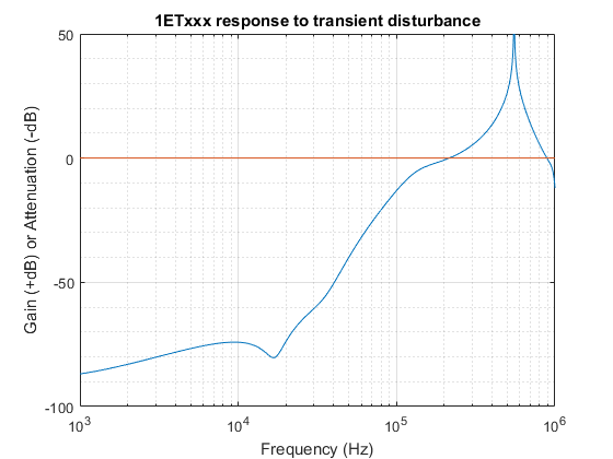 Figure 1: EIGENTAKT amplifier response to transient disturbance
This graph assumes the worst possible kind of kick: a single, infinitely short pulse, the kind you’d least expect feedback to be able to do anything about. Its spectrum is the red curve and is flat all the way to infinity. The surprise outcome is shown in blue: the pulse is effectively attenuated all the way up to 200kHz. The audible fraction is knocked down by all of 75dB. If hysteresis distortion was audible before, it certainly isn’t anymore.
Above 200khz the attenuation turns into gain. This is in accordance with an iron law of control theory which says you can’t change the past. Or in spectral terms: attenuation at one frequency must come at the expense of gain at another. We can turn that to our advantage. We can let the gain work itself up to a single, infinitely tall peak at a suitable frequency. There, around 550kHz, the amplifier will self-oscillate. Not only does that rid us of a separate oscillator circuit. The gain that’s required to get self-oscillation helps buy a lot more attenuation lower down.
When the coil gives off one of its hysteretic pops, the switching frequency makes a quick jiggle. That’s it. Any audible remainder is eliminated. Feedback is very well capable of ridding us from hysteresis distortion, thank you very much.
Of course, this rather requires that you actually do put the filter inside the loop. That, it turns out, is not what most people do. If you’ve followed the class D scene a bit, you’ll have noticed that only a minority of manufacturers have worked it out. What makes it look hard is that the output filter introduces a 180 degree phase shift right after the corner frequency. This is where most designers declare the idea dead because that’s all your phase margin eaten up there and then. Or so it seems.
Most go without any form of output feedback at all. This category includes all fully integrated class D chips.
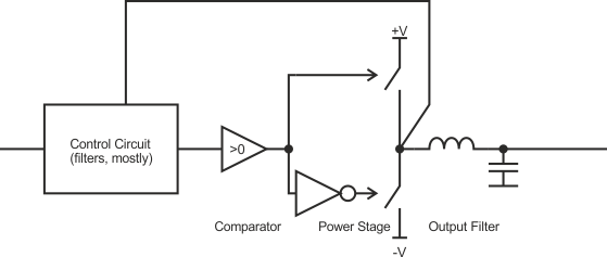
Figure 1: Feedback Done Wrong (power stage feedback)
This is clearly not useful for hi-fi. All that work to make a PWM signal containing a pristine copy of your input signal and then you let a passive filter loose on it. Even the frequency response is up for grabs. You might fix hysteresis distortion by putting in a chunky air coil (thus failing EMC and needing extra filtering to pass) but that’s hardly a priority if you can’t even keep the response flat.
A fair few manage the frequency response problem by tacking on a small amount of output feedback. Big enough to damp the resonance of the filter, small enough so you can ignore it in the loop calculation. It begs the question, precisely what signal is the feedback loop trying to match to the input signal?
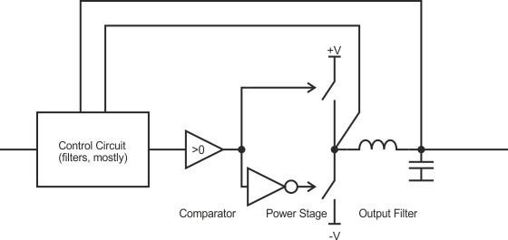
Figure 2: Feedback Done Less Wrong (mixed feedback)
Most discrete class D modules use this arrangement.
I can’t stress it enough: such compromises aren’t made for technical reasons. You have to give nothing up. It is purely a matter of maths skills. If you know how to do it, full output feedback is the unavoidable, obvious choice. There’s only one signal that your speaker sees. It’s not the square wave on the power stage. Neither is it some mix between that and the output. All your speaker ever sees is the output. Choosing any other signal for feedback is arbitrary and suboptimal.
It’s a tough assignment, yes, but not an impossible one. It makes PURIFI part of a very small coterie of class D suppliers.
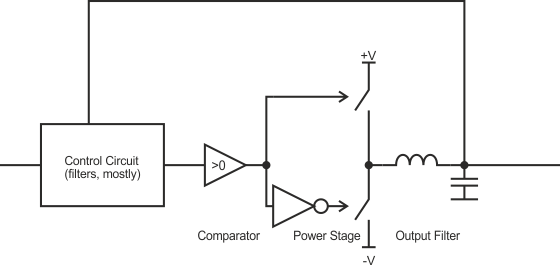
Figure 3: Feedback Done Right (full output feedback)
Among those who have full output feedback, it becomes a matter of degree of course. Compared to the Nearest Competitor, the EIGENTAKT circuit has well over ten times better error attenuation.
This was no small feat. Simply piling on more gain initially made the amplifier go unstable at ever lower amplitudes. The most relevant analyses so far i had nothing to say about this phenomenon: one study predicted the correct switching cycle at all duty cycles but not whether it was stable. It ignored how the sampling inherent in PWM changed the dynamics. Another correctly described the effect of sampling but only for small signals.
The core problem was that no sampling theory even existed that could handle unevenly spaced samples. And so, work on actual circuits was suspended until that homework was done. It was finished over the 2017 winter holidays. Finally we can predict exactly how the amplifier will behave all the way to clipping. This even includes the unequal delays caused by dead time distortion. Loop design is now done by a numerical optimization routine that finds a filter curve maximizing the combination of error attenuation and headroom. That’s when you turn on your soldering iron.
Maybe that’s the secret? Endless patience?
i: http://www.aes.org/e-lib/browse.cfm?elib=13263 and http://www.aes.org/e-lib/browse.cfm?elib=15213