The PTT6.5X04-NAA-08 is an aluminum-cone member of the famous PTT6.5X extended-stroke product family. Leveraging PURIFI’s Vibroacoustic Design Tool, an essential instrument in our Transducer IP portfolio which uses a combination of mathematical modeling, numerical optimization and FEA for automated cone geometry optimization, the aluminum cone has been designed with a targeted frequency response moving the first breakup to 5kHz at an attracted low Q value.
In the following, we show that not all methods of equalization are created equal. In particular, using a series notch reduces distortion, which does not happen with alternative methods. The proposed circuit results in an extremely clean low-pass response combined with low distortion
Driver Response in 2pi Chamber
The PTT6.5X04-NAA frequency response as measured in the PURIFI Audio chamber. The driver is flush mounted in the infinite baffle so there is no box or baffle step.

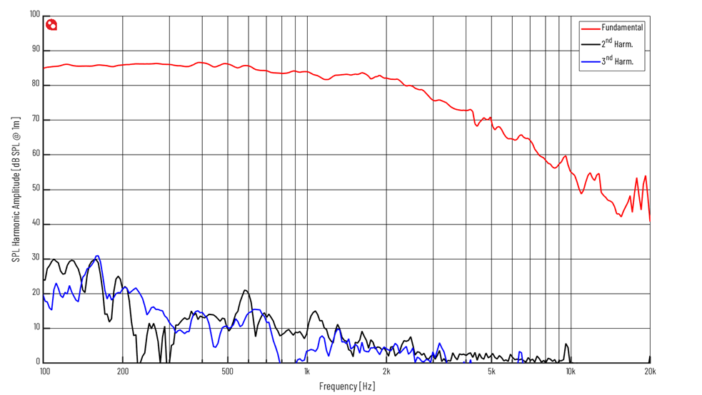
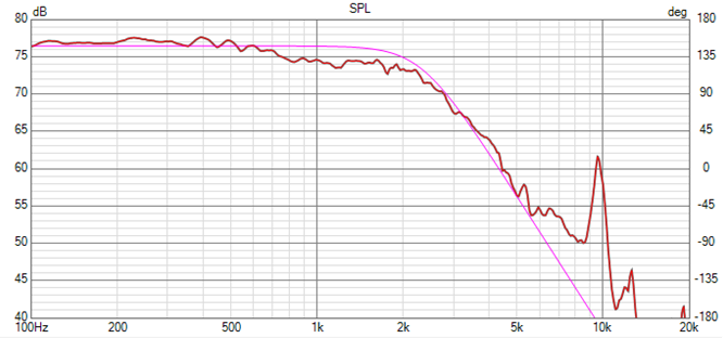
Frequency response in chamber, 0 degree. The aluminum membrane has two peaks, 5kHz and 10kHz. Note that the 3rd harmonic response shows peaks at 1.6kHz and 3.3kHz that correspond to the membrane resonances three times higher up. We will propose an equalizing tactic that not only removes the peaks from the frequency response but also removes the corresponding distortion peaks
In the following we will only show frequency response above 100Hz as the response below anyway would be dependent of the implementation of box and placement in room.
Target 3rd order low pass
The PTT6.5X04-NAA has a wide frequency response so it’s possible to achieve a 3rd order low pass acoustic response – here chosen with a corner frequency of 2300Hz.
This target is just one of many options – what’s right for your application depends on the box and tweeter chosen. In this note we will focus on the steps to tailor the response to the target. Let’s fire up VituixCad and examine the responses.
Raw response together with the 3rd order low pass target response – here chosen at 2300Hz.
Let’s first see what the response looks like with a 2nd order LC low pass: 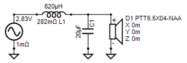
Filter config #1
The peak at 5kHz is still too high so let’s add a series notch filter: 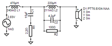
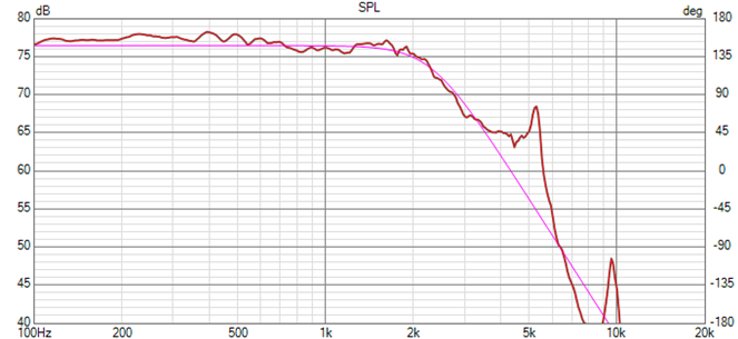
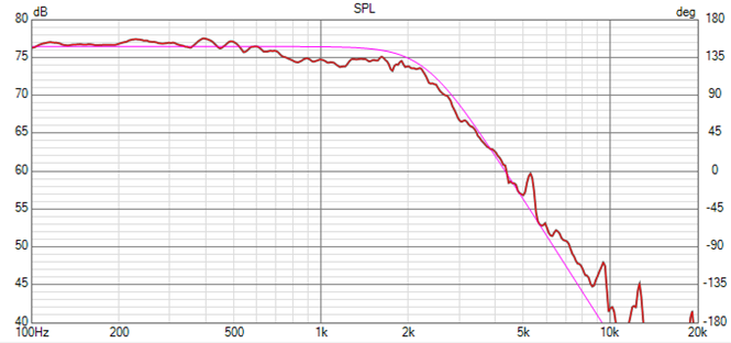
Filter config #2. This removed the 5kHz peak nicely and we have the wanted response up to 6-7kHz.
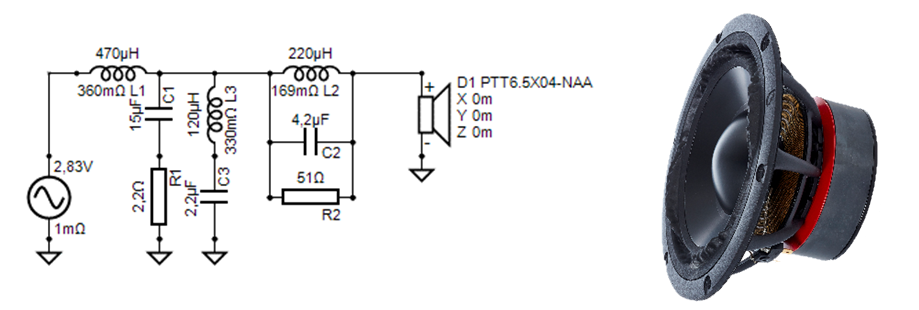
Filter config #3. With an extra parallel notch, the 10kHz peak can also be tamed.
Notice that the extra parallel notch is placed before the series notch – it's on purpose so that we have a high series impedance at the 5kHz to lower the distortion – we will come back to that.
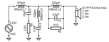
The peaks can also be flattened with parallel notches: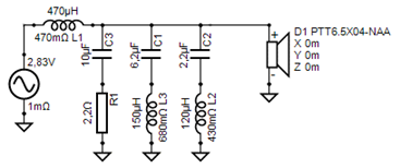
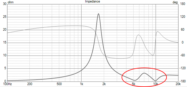
Filter Config #4. The parallel notch filter has the pitfall that the source impedance is very low at the notch frequencies.
Filter config #4. Rearranging the source in VituixCAD gives the option to show the speaker source impedance – with its low impedance at the two notch frequencies.

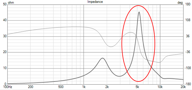
Filter config #3. The series Notch has a much higher impedance at 5kHz – 45R. This is an important feature when it comes to distortion as we shall see next
Motor Hysteresis Distortion Interaction with the Filter
A speaker motor produces distortion and in the mid-band this distortion is dominated by dynamic modulation of the coil inductance from coil motion or hysteresis effects in the iron around the voice coil. The voltage drop across an inductance is given by E=L∙i'(t). Consequently, a dynamic change of the inductance will appear as a voltage source in series with the coil and its voltage proportional to the change in inductance and the frequency of the signal (current). We can now observe the response from such a voltage source in series and the sound pressure response, i.e. see how the distortion source is shaped by the filter network and driver response. This is where the series- and parallel notch filters are vastly different as the following graph shows where the electrical voltage generator has been moved to be in series with the driver. The more series impedance is added to the driver, the less current is produced by the voltage source in series and the less SPL is produced. This why we focused on the impedance seen from the driver above.
Red curve: Series
Blue Curve: Parallel


Notice how the series notch circuit provides a substantial reduction in the reproduced distortion over a broad band centered around the peak at 5kHz. The hysteresis distortion is dominated by 3rd order harmonics and higher odd harmonics. Using the parallel notch, the peak at 5kHz will show up as a 3rd harmonic distortion peak at the generating frequency of 5kHz/3 whilst the series notch will suppress the 3rd harmonic around this subharmonic of the peak frequency (suppressing the 3rd harmonic around the 5k peak).
Measurements
In the following let’s also look at the resulting measured frequency response and THD. First the raw driver showing the 5k and 10k peaks also shows up as peaks in the 2nd harmonic distortion at these frequencies. A subharmonic 3rd harmonic peak is eyed around 1650Hz as expected but at a very low level as characteristic for PURIFI drivers. A narrow 3rd harmonic peak at 3.3kHz would appear to be the subharmonic of the 10kHz peak.
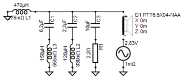
 Next, we add filter configuration #2:

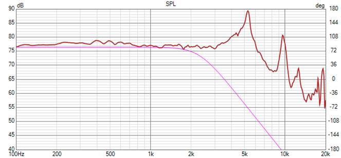
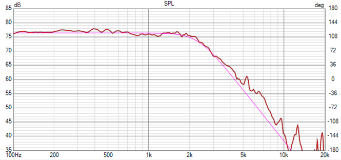
Now the THD is down in the measurement noise floor above 1-2kHz. Notice that the 1650Hz range is now lower – this is where the 3rd order frequency hit’s the 5kHz resonance. The 10kHz peak does no longer give rise to a 3rd harmonic peak in the 3.3kHz range. To further improve the SPL response, we add the 10kHz notch on top of the series 5khz notch, Filter config #3:

Extremely clean SPL and distortion response and no more sign of any resonances. It is a challenge to find a matching tweeter with such low distortion.
The next figure compares parallel to serial notch filtering: Solid – Serial 5kHz Notch,
Dashed - Parallel Notch.

The parallel notch filter response gives as expected around 10dB higher THD in the 1.65kHz area where the 3rd order harmonic frequency gets amplified by the SPL peak at 5kHz of the cone. The series notch is suppressing the peak by providing a much higher drive impedance to the driver at the peak frequency.
Conclusions
The PTT6.5X04-NAA-08 aluminum cone driver has a very well-behaved frequency response with two break-up peaks at 5kHz and 10kHz.
With a simple 2nd order low pass filter and serial notches, the peaks are virtually removed, and the frequency response approaches accurately a chosen 3rd order lowpass target response. Moreover, the THD is driven down into the noise floor of the measurement setup. There is no need to resort to extremely sharp filters or a low cross over frequency to handle the peaks using the shown methodology.
A filter for a final speaker-box application needs to have baffle step correction which was left out in the shown examples to allow high precision measurements in the 2pi anechoic chamber.
Finally, it was shown how different filter configurations resulting in approximately the same SPL response can have significantly different impact on the distortion of the system.